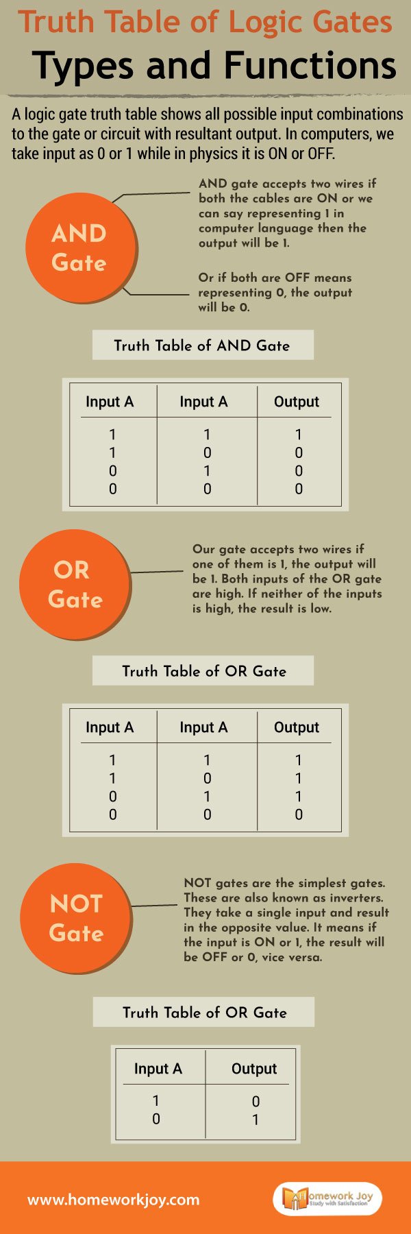
A logic gate truth table shows all possible input combinations to the gate or circuit with resultant output. In computers, we take input as 0 or 1 while in physics, it is ON or OFF.
Also, to see some of our latest posts, click the link below:
What are Constants in Math | Definition, and Examples
What Are the Differences Between C and C++?
Let’s move ahead to know the truth table of logic gates according to the Boolean Algebra.
AND Gate
AND gate accepts two wires. If both the cables are ON or we can say representing 1 in computer language, then the output will be 1.
Or if both are OFF means representing 0, the output will be 0.
Truth Table of AND Gate
Input A Input B Output
1 1 1
1 0 0
0 1 0
0 0 0
OR Gate
Our gate accepts two wires. If one of them is 1, the output will be 1. Both inputs of the OR gate are high. If neither of the inputs is high, the result is low.
Truth Table of OR Gate
Input A Input B Output
1 1 1
1 0 1
0 1 1
0 0 0
NOT Gate
NOT gates are the simplest gates. These are also known as inverters. They take a single input and result in the opposite value. It means if the input is ON or 1, the result will be OFF or 0, vice versa.
Truth Table of NOT Gate
Input A Output
1 0
0 1
Furthermore, there are other gates which are more complex than the ones mentioned above. So let’s see what these are.
XOR Gate
The XOR gate in a similar way like logic gates “or/either.” So XOR logic gate the output is true if either, but not both, the inputs are true. It is a two gate which takes two-way information. Besides this, the output is false if both inputs are false or if both are true. For differentiating it from other devices, inventors sometimes call it NOT gate.
Truth Table of XOR Gate
Input A Input B Output
0 0 0
0 1 1
1 0 1
1 1 0
NAND Gate
The NAND gate is a little complex than other gates, as it is the combination of two gates. The gate operated as an AND gate and followed by NOT gate. Thus it operates logically “and” followed by the negation. It means the output is false if both the inputs are true, otherwise false.
Truth Table of NAND Gate
Input A Input B Output
0 0 1
0 1 1
1 0 1
1 1 0
NOR Gate
NOR gate is the mixture of the OR gate, followed by the inverter. So the output is true if both inputs are false and vice versa.
Truth Table of NOR Gate
Input A Input B Output
0 0 1
0 1 0
1 0 0
1 1 0
Therefore it was the illustration of the truth table of logic gates. This topic has its importance for physics, computer science, and philosophy students. So you can take help from the above truth tables to understand different types of logic gates. Also, to know more about similar topics, get instant online assignment help from our experts.